
AYUCR
Pencam Controller V1.3
Assembly Instructions
| Part | Identification |
|---|---|
| Printed circuit board | V1.3 |
| Microchip PIC preprogrammed with the controller firmware | PIC 16F819 |
| 18 pin DIP socket for CPU | |
| 8 pin solid state relay | NEC PS7141-2A |
| Small arming switch | Alco TSS-11 |
| Acceleration Switch | 2037-1-000 |
| Status LED | |
| 470 Ohm LED current limiting resistor | Yellow Violet Brown |
| 2.2K Ohm current limiting resistors (3) | Red Red Red |
| 100K Ohm Serial port resistor | Brown Black Yellow |
| 5V voltage regulator | 78L05 |
| 0.1 uF tantalum decoupling capacitor | V1 |
| 4 Pin connector for shutter | |
| 3 Pin connector for serial port | |
| Battery Clips (2) | |
| Power jumper | Red |
| 470 uF electrolytic capacitor | 470uF |
Assembly instructions for older (pre-version 1.3) Pencam Controller kits can be found here
Building and Testing the Camera Controller
To assemble the Pencam Controller you will need the following tools
- Soldering iron (15 or 20 watt)
- Thin solder
- Small pliers
- Wire cutters
- Small file or emery board
- Alcohol and a toothbrush to clean solder residue
- Masking tape to hold some parts in place while soldering
- 12 Volt N-size battery. Radio shack sells these as "remote control" batteries
- Patience!
Tips
- Read all instructions first and make sure you understand what each step is asking you to do.
- Work slowly and test fit each part before you solder to make sure it's placement is correct.
- All resistors are soldered on to the back side of the circuit board. Make sure you solder parts on the correct side
- Certain parts have polarity and will not work if inserted backwards. Make sure you can itentify the orientation marks of these parts and insert them correctly.
- Flux residue from soldering can contaminate the board and prevent it from working properly. Clean off solder residue with alcohol and a soft tooth brush as you go. Once the board is fully populated cleaning it will be more difficult.
- Check solder joints from both sides to ensure a good joint. Don't use too much solder. Solder joints should be concave like fin fillets.
Part I
In this part of the assembly you will first build the minimal circuit. This won't do much, just flash the LED, but it helps to diagnose certain building errors early when they can be easily fixed. Take your time and test fit each part to make sure you are inserting it in the correct holes.
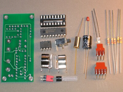 |
Step 1: Identify all of the parts using the parts list above for reference. |
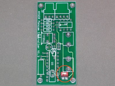 |
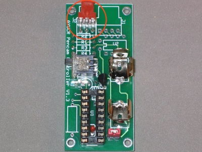
Step 2: Identify the top side (front) of the circuit board. It should say "AYUCR Pencam Controller" Place the power jumper through its holes on the front of the board and solder in place from the back side. You may need to file the pins slightly to get them to fit through. the holes. Clean any solder residue using a toothbrush and alcohol. |
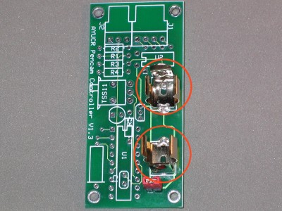 |
Step 3: Solder the battery clips to the front side of the circuit board, again, soldering from the back side of the board. The clips must face each other so the battery may be inserted. The battery clip joints must be strong. Use a healthy amount of solder completely filling the holes. |
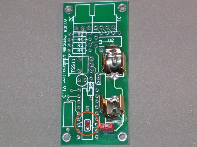 |
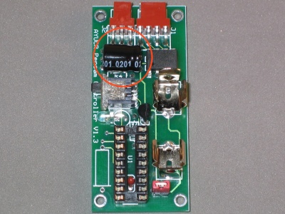
Step 4: Solder the decoupling capacitor in place as shown. There is a small plus sign with a white band on it indicating its orientation. This pin is on top. Trim the leads and clean any solder residue. |
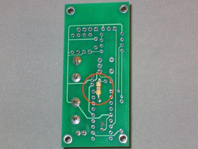 |
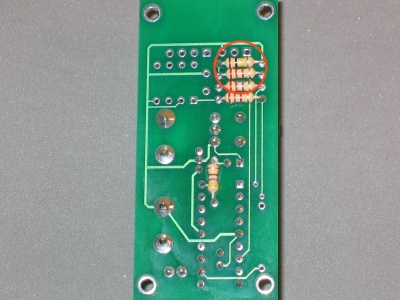
Step 5: Solder 470 Ohm (Yellow Voilet Brown) LED current limiting resistor in place as shown. This resistor is placed on the back side of the circuit board while soldering from the front. Clip the extra leads off as close as you can to the board and clean any solder residue. |
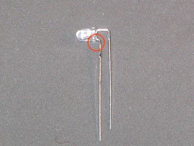 |
Step 6: Bend the leads of the LED as shown. The short lead must be on the left. There is also a flat side of the LED to identify this lead (circled). This lead goes in the square pad on the circuit board. If you do this backwards the LED will not light. |
 |
Step 7: Solder the LED in place as shown. The LED should face left. Trim the excess leads and clean any solder residue. |
 |
Step 8: Solder the voltage regulator in place as shown. The orientation is important. The flat side faces right as you look at the board from the front. Snip off the extra leads close to the circuit board. As always, remove any solder residue as you go. |
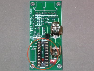 |
Step 9: Test fit the IC socket. It fits over the decoupling capacitor from step 4. It must sit flat on the board and not touch the solder joint from the resistor on the back of the board. When you are sure it sits cleanly solder it in place. The notch should face up as it serves and an indicator for inserting the CPU. Clean any solder residue. |
Testing and Toubleshooting
Once you have gotten this far you should be able to test the circuit. Make sure there is no flux residue left on the board. It is a good idea to test the PIC socket using a multimeter before inserting the PIC. Place a fresh 12V battery in the battery holder with the positive side up. Wrap the battery in tape to prevent it from shorting on the metal battery clips. Power the cicuit on by placing the red power jumper on the power header. Using the minus side of the battery as your ground Pin 14 (start at the upper left pin which is pin 1 and count counter-clockwise to pin 14. It is the middle pin on the right side of the socket) should have +5V and pin 5 should read 0V. If not recheck all of your work before proceeding.
 |
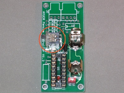
Step 10: Turn the power off by pulling the red jumper. Insert the PIC processor in its socket with the notch on the chip oriented up. The notch on the socket and the chip should coincide (circled in photo). Power up the unit again. The Pencam Controller LED should blink slowly indicating the unit is powered up in standby mode. |
If the LED does not light or the LED lights but stays lit remove power and debug the circuit
- Double check all your connections as well as check for solder residue.
- Check the output of the voltage regulator (pin 1) This should be 5V.
- Check the voltage across the LED. It should fluctuate from zero to +1.6V If you see the voltage fluctuation but the LED isn't blinking then the LED may be reversed.
- Check that the battery voltage is at least 6V. Try a different battery if less.
Part II
Time to finish the circuit. Remove the battery from the battery holder before continuing. Follow the remaining directions to complete the Camera Controller.
 |
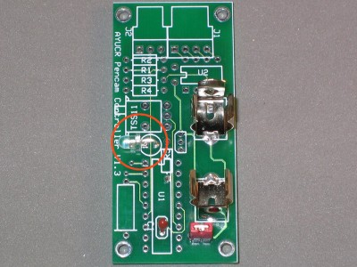
Step 11: Solder the arming switch in place as shown. It should fit snugly to the board. Use healthy solder joints to hold it securely in place. Again, clean any solder residue. |
 |
Step 12: Solder two 2.2K ohm (Red Red Red) current limiting resistors in place as shown. These are soldered to the back side of the board. Trim the leads and clean any solder residue. |
 |
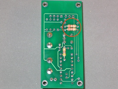
Step 13: Solder the two serial port resistors in place as shown. These are soldered to the back side of the board. The 100K ohm (Brown Black Yellow) resistor goes in the top set of holes and the 2.2K ohm (Red Red Red) resistor goes in the bottom set. Trim the leads and clean any solder residue. |
 |
Step 14: Solder the serial port header in place as shown. Use healthy solder joints for strength. clean any solder residue. |
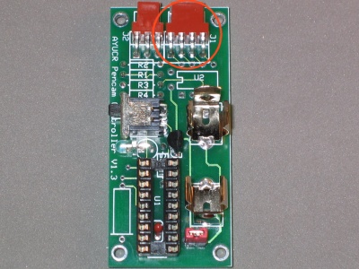 |
Step 15: Solder the camera interface header in place as shown. Use healthy solder joints for strength. clean any solder residue. |
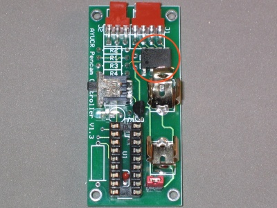 |
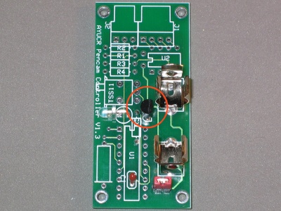
Step 16: Solder the solid state relay in place as shown. The dot on the top of the package denotes pin one and coresponds to the square . Clean any solder residue. |
 |
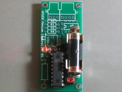
Step 17: Solder the 470uF capacitor in place as shown. The negative lead is identified by a white band along the side of the capacitor. The lead goes in the topmost hole. The capacitor should lay flat on the board. You can use a bit of hot melt glue to hold it in place. Trim the leads and clean any residue. |
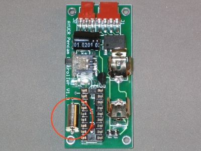 |
Step 18: Solder the G-switch in place as shown. The flange must face down or the G-switch won't detect liftoff. Make sure the flange does not touch the lower solder pad. Trim the leads and clean any solder residue. |
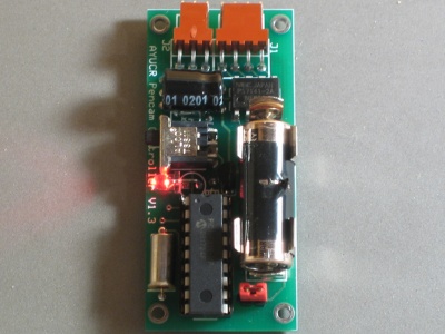 |
Done! |
You should now test the parts of the circuit you added in part II. Power up the Pencam Controllern by placing the red jumper on the power header pins. Make sure the arming switch is up (standby mode) The LED should blink slowly, about once every two seconds. Arm the controller by sliding the arming switch down. The LED should now blink faster. Disarm the controller. To test the serial port see the instructions for using the programming software.
Good work! Make sure you understand how the timer works and it is tested and trimmed prior to your first flight.
See the Articles section of the website to find instructions on assembling a cable to interface the Pencam Controller with a PC or Palm.