
AYUCR
Pencam Controller
User Manual
Features
- PIC Microcontroller based programmable Pencam controller (upgradable)
- Self-contained with built-in G-switch arming
- Supports single shot and continuous (movie) modes
- LED for flight status
- Field programmable via serial port using laptop computer, Palm Pilot etc.
- Palm-Pilot software for field programming included
- Prevents Pencam from turning off when armed on the pad
- Program is stored in non-volitile EEPROM memory and does not require battery power
- Logging of number of pictures taken during flight
- Firmware flash upgradable via on-board serial port
Specifications
| Dimensions (HxWxD) | 2.5"x1.125"x5/8" |
| Weight | 12g (19g w/ battery) |
| Power Consumption | 4-12mA typical |
| Battery Life | 4 hours minimum |
| Power Requirements | 12V remote Battery or 6V-12V via external power connector |
| Serial Port | 2400 Baud, 8bits, No Parity, 1 Stop bit |
| G-Switch Rating | 2.1G +/- 10% |
Schematic
Several connections in the schematic cross over each other. Unless there is a dot at the juction the lines are not connected. This scematic is now outdated. The current design uses a chip with and internal xtal so the external one is no longer used. The two relays have been replaced with a dual opto relay and pins 2 and 18 on the PIC were swapped to ease board layout. The schematic will be updated soon.
 |
| Click image for a larger view |
Programable Flight Parameters
| Parameter | Units | Explanation |
|---|---|---|
| Launch Detect | 1/100 sec | How long the rocket must accelerate at greater than 2.1 Gs to initiate liftoff. Range is 1/100 second to 2.5 seconds. A good choice is 20 (2/10 sec). Too short and the controller will be sensitive to bumps and shakes. Too long and the motor may burn out before launch is detected. |
| Launch Delay | 1/10 sec | Delay between launch detect and first picture. The default is 0 which gives shots during boost. If you only want shots starting at apogee add a delay for boost and coast here. |
| Number of Groups | Count | Pictures can be divided into any number of groups with a delay between groups. Use this to program the number of groups of pictues to take. |
| Number of Pictures | Count | This is the number of Pictures to take per group. If the Number of Groups is set to 1 (one) then this is effectively the number of pictures to take total. |
| Picture Interval | 1/10 sec | Delay between each picture in each group. The minimum is dependant on the camera used. |
| Group Interval | seconds | Delay between each group of pictures. There is no need to account for the Picture Interval when figuring the Group Interval. If the Picture Interval is 3 seconds and the Group Interval is 10 seconds the time between the last picture of the first group and the first picture of the second group will be 10 seconds not 13. |
| Shutter Speed | 1/10 sec or sec | The amount of time the controller trips the shutter release button for. For single shot mode measured in 1/10 sec. For Continuous mode measured in seconds. |
| Mode | 0 or 1 | Whether the Pencam operates in single shot mode (0) or continuous mode (1) |
| Poweron Time | 1/10 sec | Amount of time mode button must be depressed to power up camera. If this value is too large some cameras will power up and then back down again. (V1.3+) |
| Cycle Count | Count | Number of Mode button presses make up a full cycle through the menu options. Used as a "keep alive" signal to prevent the camera from going to sleep on the pad. The count is important so that the camera returns to the same mode after each cycling. (V1.3+) |
| Cycle Pacing | 1/10 sec | How long to pause beteen mode presses when cycling. Shorter times result in faster cycling. (V1.3+) |
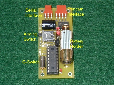
Powering the Pencam Controller
The Pencam Controller is designed to be powered by a 12V remote control battery (Radio Shack part 23-154) in the on-board battery holder. Iinsert the battery with the plus side facing up as shown. The battery is held very tightly. You may need a pair of pliers to remove it.
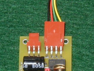
Connecting the Pencam
The Pencam interfaces with the controller using the 4 pin connector shown in the photo below. Pins 1 and 2 (leftmost) connect to the Mode button on the Pencam and pins 3 and 4 connect to the shutter button.
| Pin Number | Wire Color | Function |
|---|---|---|
| 1 | Black | Mode |
| 2 | Red | Mode |
| 3 | Green | Shutter |
| 4 | Yellow | Shutter |
Using the Camera Controller
Powering up the Controller - To power up the Controller place the red power jumper over the two pins on the power header. The LED should flash when powered up. To conserve the battery you should power the controller down unless you are flying it or programming it.
Standby Mode - Moving the Arming Switch to the OFF position (Up) puts the controller in Standby Mode. A slowly flashing LED, about 1 flash every two seconds, confirms the unit is in standby mode. This is the normal mode for controller unless the rocket is on the pad and ready to fly. In this mode the controller monitors the serial port and will accept commands to program the unit or dump the current flight parameters to the serial port.
Armed Mode - Moving the Arming Switch to the ON position (Down) arms the unit. A quickly flashing LED indicates the controller is Armed. When Armed the controller powers up the Pencam, places it in single shot o continuous mode depending on the value of the Mode parameter and waits for launch by watching the G-Switch. If it senses greater than 2.1 Gs for the duration specified by the Launch Detect parameter it will immediately enter Flight Mode and begin the picture cycle. The Pencam is powered on as long as the controller is armed and will not power down. This is accomplished via a periodic keep-alive signal. You can disarm the controller and return to Standby Mode by moving the Arming Switch to the OFF position. The controller will release the Pencam and allow it to power down normally when disarmed. In order to configure the Pencam properly for flight the Pencam must be powered down prior to arming.
Note: Earlier versions of the Controller did not work with some newer Pencams. The controller would wake the camera up on arm but it would immediate turn off again. There is a firmware revision the corrects this.
Flight Mode - Once the controller has sensed liftoff it enters flight mode and will begin taking pictures (or a movie if in continuous mode). If a Launch Delay has been specified the controller pauses that amount of time and then begins taking pictures according to the program. Once the program has run its course the unit enters Post-Flight Mode.
Post-Flight Mode - After the controller has taken the programmed number of pictures it enters Post-Flight Mode. It turns off the LED and puts itself into a low-power mode to help save the batteries. To reset the controller and enter Standby Mode place the Arming Switch in the OFF position. This wakes the unit up and it will flash out the number of pictures taken during flight. After that you should notice the slow flashing LED indicating Standby Mode. As the Arming Switch may be the only thing easily accessable from outside the rocket the picture count is designed to provide some quick feedback after flight. The picture count display only shows the number of pictures the controller tried to take. If there was a power failure in flight this number may be less than expected. This display cannot be used to diagnose problems with the camera or problems with Trimming. You should always check the Pencam's exposure counter to see if it agrees with the controller.
Single Shot Mode
To take a sequence of still frames use the Pencam Controller in single shot mode. The Mode parameter is set to 0 and the Shutter Speed parameter should be set to 3/10 second. The other parameters should be set according to the desired photo sequence.
Continuous Mode
To take a movie use the Pencam Controller in continuous mode. The Mode parameter is set to 1 and the Shutter Speed parameter should be set to The length of the movie in seconds. Normally the Shutter Speed parameter is measured in 1/10 seconds but for continuous mode it is measured in seconds. You can also configure the Launch Detect and Launch Delay parameters but all others are not applicable and will be ignored.
Typical Flight Timeline
Below is a flight timeline from a sample flight to help clarify how the controller works.
| Flight Parameter | Value |
|---|---|
| Launch Detect | 20/100 sec |
| Launch Delay | 0 sec |
| Number of Groups | 3 |
| Number of Pictures | 4 |
| Picture Interval | 2 sec |
| Group Interval | 5 sec |
| Shutter Speed | 3/10 sec |
| Mode | 0 |
| Time | Event |
|---|---|
| -0.0 | Altimeter is armed. LED flashes quickly and controller waits for launch detect |
| 0.0 | Launch. Altimeter senses launch and confirms G-Switch closed for 20/100 sec |
| 0.2 | Valid launch. There is no delay before the first picture specified so the controller immediately begins to take pictures. |
| 2.2 | Picture 2 |
| 4.2 | Picture 3 |
| 6.2 | Picture 4 followed by a 5 second Group Interval |
| 11.2 | Picture 5 |
| 13.2 | Picture 6 |
| 15.2 | Picture 7 |
| 17.2 | Picture 8 followed by a 5 second Group Interval |
| 22.2 | Picture 9 |
| 24.2 | Picture 10 |
| 26.2 | Picture 11 |
| 28.2 | Picture 12 |
| 28.5 | Immediately following last picture controller enters Post-Flight Mode. LED is off and the controller waits to be disarmed. |
| 28.5+X | Arm Switch to OFF. LED flashes 12 times to indicate 12 pictures were taken. Enters Standby Mode. |
Serial Commands
The controller recognizes seven commands via the serial port. One programs the controller with new flight parameters and the other instructs the controller to dump the current program to the serial port. These commands can be sent from the serial port of any computer with the serial port set to 24008N1 or 2400 baud, 8 data bits, no parity and 1 stop bit.
The serial port uses a three pin interface. Looking at the picture with the serial port facing up and going left to right the pinout is as follows
| Pin | Function |
|---|---|
| 1 | TxD |
| 2 | RxD |
| 3 | GND |
Command Summary
| Command | Function |
|---|---|
| /P | Accept new flight parameters (for use with Palm software) |
| /D | Dump settings (for use with Palm software) |
| /N | Prompt for new flight parameters using a simple interface |
| /R | Display the current fight parameters in human-readable format |
| /M | Report controller model number ("APC" in this case) (V2.0+) |
| /V | Report firmware version |
| /S | Test Shutter |
| /B | Enter Bootloader (V2.0+) |
| /Z | Return the number of bytes sent and received by the /P and /D commands (V1.3+) |
Program - To download flight parameters to the controller the serial programming command is "/P" followed by eight or sixteen bytes depending on the firmware revision. V1.3 and later use sixteen bytes. Earlier versions use eight bytes.
/ P p1 p2 p3 p4 p5 p6 p7 p8 p9 p10 p11 p12 p13 p14 p15 p16
where the data bytes are defined as follows
| Data Byte | Flight Parameter |
|---|---|
| p1 | Launch Detect (1/100 sec) |
| p2 | Launch Delay (1/10 sec) |
| p3 | Number of Groups |
| p4 | Number of Pictures |
| p5 | Picture Interval (1/10 sec) |
| p6 | Group Interval (seconds) |
| p7 | Shutter Speed (1/10 sec) |
| p8 | Mode (0 or 1) |
| p9 | Poweron Time (1/10 sec) |
| p10 | Cycle Count |
| p11 | Cycle Pacing (1/10 sec) |
| p12 | Not used |
| p13 | Not used |
| p14 | Not used |
| p15 | Not used |
| p16 | Not used |
The program that communicates with the controller should confirm that the controller responds with two bytes "OK" to ensure the command was received successfully. The controller will report "TO" if the eight parameter bytes are not received within a few seconds.
Dump - The command to instruct the controller to send its current Flight Parameters is "/D". Eight databytes in the same order sent in the Program Command will be be sent from the controller followed by the bytes "OK"
New Program - This provides a simple user interface for accepting new flight parameters. It prompts for each parameter one at a time and allows the user to change the current value using the '+' and '-' keys. Type '/N' to enter this command. The prompts are as follows:
| Prompt | Flight Parameter |
|---|---|
| LD- | Launch Detect (1/100 sec) |
| DL- | Launch Delay (1/10 sec) |
| #G- | Number of Groups |
| #P- | Number of Pictures |
| PI- | Picture Interval (1/10 sec) |
| GI- | Group Interval (seconds) |
| SS- | Shutter Speed (1/10 sec) |
| MD- | Servo Mode (0 or 1) |
| PT- | Poweron Time (1/10 sec) |
| CC- | Cycle Count |
| CP- | Cycle Pacing (1/10 sec) |
To increase the current value press the '+' key. To decrease the value press the '-' key. To reset the value to zero press the '0' key. To accept the current value press Enter. To canel press Esc, any changes will be discarded. Important: make sure that "Local Echo" is off in you terminal program or you will see a lot of garbage on the screen.
Read Program - '/R' displays the current flight parameters in a human-readable format. The values are labled the same as the prompts in the New program command.
Bootloader - '/B' Puts controller in Bootloader mode. Controller must be powered off and on to return to normal operation. See below for more information
Version - Enter '/V' to see the current firmare version.
Model - Enter '/M' to see the model number of the controller. APC for AYUCR Pencam Controller.
Shutter Test - Enter '/S' to test the shutter. The controller will take one picture. This is useful for setting the Shutter Speed parameter.
Program Size - Enter /Z to get the number of bytes in a program. This is intended to be used by software that interfaces with the controller. If the /Z command returns "ER" then the firmware is an older revision and has an 8 byte flight program. Otherwise a single binary byte is returned followed by OK indicating the length of the program.
Errors
The controller will report the following errors. "TO" is reported if a command letter is not entered after the slash character within 2 seconds. "ER" is reported if an unknown command is entered.
Configuring cameras
Below are the values the configuration values that are known to work with various cameras. Every camera is slightly different. If your camera isn't listed here and you would like to contribute to this list please email me.
| Camera | Poweron Time | Cycle Count | Cycle Pacing | Notes |
|---|---|---|---|---|
| Aiptek Pencam Trio | 5 | 5 | 3 | |
| Aiptek Pencam VGA | 5 | 5 | 3 | |
| Aiptek Megacam | 10 | 4 | 3 | Camera must be empty (no pictures taken) for cycle count of 4 to work properly |