
AYUCR
Camera Controller V2.1
Assembly Instructions
These instructions are for the newer version of the kit based on the 18 pin PIC 18F819. For the original version based on the PIC 12CE673 click here.
Parts List
| Part | Identification |
|---|---|
| Printed circuit board | |
| Microchip PIC preprogrammed with the controller firmware | PIC16F819 |
| 18 pin DIP socket for CPU | |
| Ceramic Resonator | 4000A |
| 6 pin solid state relay | AQV210E |
| Small pushbutton switch | Omron B3F |
| Acceleration Switch | 2037-1-000 |
| Status LED | |
| 470 Ohm LED current limiting resistor | Yellow Violet Brown |
| 2.2K Ohm current limiting resistors (2) | Red Red Red |
| 100K Ohm Serial port resistor | Brown Black Yellow |
| 5V voltage regulator | LM78L05 |
| 0.1 uF tantalum decoupling capacitor | K5M |
| 4 Pin connector for shutter/power | |
| 3 Pin connector for serial port | |
| Battery Clips (2) | |
| Power jumper | Red |
| 470 uF electrolytic capacitor | 16V 470 uF |
Building and Testing the Camera Controller
To assemble the Camera Controller you will need the following tools
- Soldering iron (15 or 20 watt)
- Solder
- Small pliers
- Wire cutters
- Alcohol and a toothbrush to clean solder residue
- Masking tape to hold some parts in place while soldering
- 12 Volt N-size battery. Radio shack sells these as "remote control" batteries
- Patience!
Tips
- Read all instructions first and make sure you understand what each step is asking you to do.
- Work slowly and test fit each part before you solder to make sure it's placement is correct.
- Solder all parts from the back side of the board.
- Certain parts have polarity and will not work if inserted backwards. Make sure you can itentify the orientation marks of these parts and insert them correctly.
- Flux residue from soldering can contaminate the board and prevent it from working properly. Clean off solder residue with alcohol and a soft tooth brush as you go. Once the board is fully populated cleaning it may be more difficult.
- Check solder joints from both sides to ensure a good joint. Don't use too much solder. Solder joints should be concave like fin fillets not like balls.
- Use proper soldering technique. Use tip of iron to heat the joint between the board and the part for a few seconds. Then feed solder to the joint. Solder does not bond properly with cold joints.
- The plated-through holes are great for making good solder joints they are difficult to unsolder. Again, Doublecheck your work before you solder to make sure the parts are oriented properly and in the right place.
Part I
In this part of the assembly you will first build the minimal circuit. This won't do much, just flash the LED, but it helps to diagnose certain building errors early when they can be easily fixed. Take your time and test fit each part to make sure you are inserting it in the correct holes.
 |
Step 1: Identify all of the parts using the parts list above for reference. If you are missing any parts please contact me for replacements. |
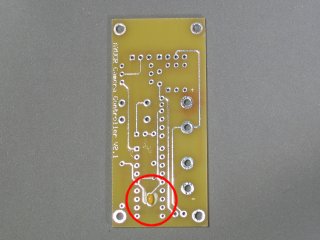 |
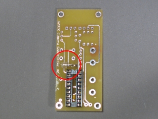
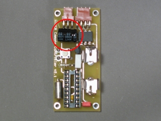
Step 2: Identify the top side of the board. It should say "AYUCR Camera Controller" down the side. Solder the small decoupling capacitor in the location shown in the photo. Remember, place the part as shown on the top side of the board but solder it from the bottom side. |
 |
Step 3: Solder a 470 Ohm (Yellow Violet Brown) in the location indicated on the bottom side of the board. This is important. Soldering the part to the front side of the board (the side with the words AYUCR Camera Controller") will interfere with parts in later steps. Stop here and check your work. It is a good idea to clean up solder and flux residue as you go. Too much flux residue can make the circuit behave eratically or not at all. |
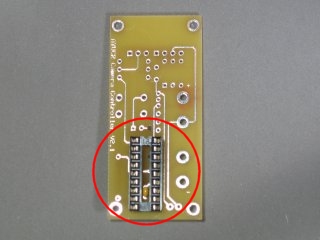 |
Step 4: Solder the 18 pin DIP socket in place as shown. It should fit over the capacitor from step 2. There is a notch in one end of the socket that should face up. This notch isused to indicate which way to insert the chip later. If the socket is backwards it may confuse you when you go to insert the chip later |
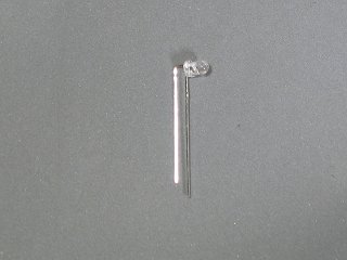 |
Step 5: Bend the leads of the LED as shown. The right-hand lead is the cathode and corresponds to the flat spot on the LED. The idea here is the LED will be mounted on a right angle to the circuit board. If the board is mounted with the board perpendicular to the outside of the airframe then the LED will shine out the hole for arming switch access. |
 |
Step 6: Solder the LED in place as shown. Make sure you observe polarity and solder the cathode (flat spot on LED) to the square pad. Clip the leads flush with the board. |
 |
Step 7: Solder the 2 pin power header in place near the lower edge of the board. Since this part will undergo the stress of placing and removing the power jumper make sure you make a strong solder connection. |
 |
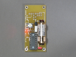
Step 8: Solder the ceramic resonator to the top side of the board as shown. Orientation is not important. |
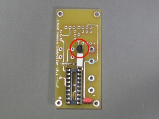 |
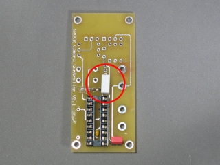
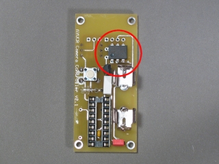
Step 9: Solder the voltage regulator to the top side of the board as shown. The flat side must face right. |
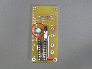 |
Step 10: Solder the pushbutton to the top side of the board as shown. Orientation is not important. |
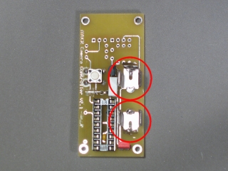 |
Step 11: Solder the two battery clips to the board facing each other. The battery will be inserted between them. Again, make sure these solder joints are strong. This will require more solder than the other solder joints. The hole in the board should be completely filled. |
Testing and Toubleshooting
Once you have gotten this far you should be able to test the circuit. Make sure there is no flux residue left on the board. It is a good idea to test the PIC socket using a multimeter before inserting the PIC. Place a fresh 12V battery in the battery holder with the positive side up. Power the cicuit on by placing the red power jumper on the power header. Using the minus side of the battery as your ground Pin 14 (center pin right-hand side of socket) should have +5V and pin 5 (center pin left-hand side of socket) should have 0V. If not recheck all of your work before proceeding.
Turn the power off by pulling the red jumper. Insert the PIC processor in its socket with the notch on the chip oriented up. The notch on the socket should coincide. Power up the unit again. The Camera Controller LED should blink slowly indicating the unit is powered up in standby mode.
If the LED does not light or the LED lights but stays lit remove power and debug the circuit
- Double check all your connections as well as check for flux residue.
- Check the output of the voltage regulator (pin 1) This should be 5V.
- Check the voltage across the LED. It should fluctuate from zero to +1.6V If you see the voltage fluctuation the LED may be reversed.
- Check that the battery voltage is at least 6V.
Part II
Time to finish the circuit. Remove the battery from the battery holder before continuing. Follow the remaining directions to complete the Camera Controller.
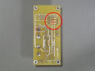 |
Step 12: Solder the 100K ohm (Brown Black Yellow) and the two 2.2K ohm resistors to the bottom side of the board as shown. The 100K ohm resistor goes on the upper set of holes and the 2.2K ohm resistors are in the lower two set of holes. Orientation is not important. |
 |
Step 13: Solder the 6-pin relay in place with the dot or notch facing to the left. |
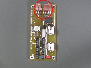 |
Step 14: Solder the 3 pin serial connector and the 4 pin shutter/power connector in place as shown. The solder joints should be strong to withstand the stress of plugging and unplugging the connectors. |
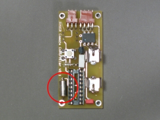 |
Step 15: Solder the acceleration switch in place. The flange should face aft. If the acceleration switch is soldered in backwards it won't sense liftoff. |
 |
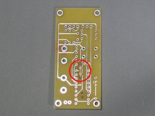
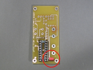
Step 16: Identify the negative lead of the 470uF backup capacitor. It is the shorter of the two. Bend both leads over at a right angle and solder the capacitor in place where indicated in the photo. The negative lead goes in the upper hole. The capacitor will be lying down to give it a lower profile. |
You should now test the parts of the circuit you added in part II. Power up the timer by placing the red jumper on the power header pins. Make sure the arming switch is up (standby mode) The LED should blink slowly, about once every two seconds. Arm the timer by pressing the button. The LED should now blink faster. Disarm the controller and return to standby by pressing the button again. To test the serial port see the instructions for using the programming software.
Good work! Make sure you understand how the timer works and it is tested and trimmed prior to your first flight.
See the Articles section of the website to find instructions on assembling a cable to interface the Camera Controller with a PC or Palm.