The heart of the project is the payload compartment. This houses the camera, timer circuit, acceleration switch and 9V battery. It is also the most valuable and delicate portion of the rocket. As such I wanted to make sure that it would be protected during flight and be able to withstand a hard landing without damage. It's a good thing too, on its first flight the chutes for the payload section and booster tangled. The whole rocket came down under the booster chute and hit hard. The camera however was undamaged.
Since the camera was small enough to fit inside a 3 inch tube coupler I decided to build a payload compartment that could hold the camera. This helps protect the camera and holds it firmly. This tube coupler would then slide into the payload section and be held in place by two screws through the airframe. A riser on the top of the compartment would hold the battery and acceleration switch which must be mounted vertically. One benefit of this arrangement is it allows me to prep the camera and electronics without having to reach inside the airframe.
| | |
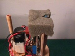
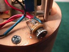
| Matching cutouts for arming plug, lens, display window and flash-mode button | Inside of compartment showing screw beds and plate that holds camera flush | Timer's orange and yellow shutter leads and red and black power leads |
The tube coupler that holds the camera is pretty simple. It has a centering ring epoxied to its bottom end which provides strength and something to grab onto when pulling the payload compartment out of the airframe. It has a plate inside, made from 1/8" plywood that holds the camera flush against the lens opening. As luck would have it there is a bulge on the shutter button side of the camera that rests perfectly on the edge of this plate that keeps the camera from sliding backwards under boost. There are two semi-circular screw beds made from hardwood dowels that accept the top plate and extension. There are also cutouts for the camera lens, LCD readout and flash-mode button. The reason lens cutout is obvious. The cutouts for LCD readout and flash-mode button were added after several flights had been made. The LCD readout allows me to see immediately on recovery if any pictures have been taken and the flash-mode button lets me set the built in flash from auto to off when the rocket is on the launch pad and turned on.
 |  |  |
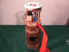
| Camera inserted in compartment with shutter wires attached to timer circuit | foam padding on top of camera with timer power connection exposed | Top plate screwed to payload compartment. Risers, battery clip visible |
The plate that holds the camera also creates a small compartment that I use to house the timer circuit. It fits in there perfectly and works out well because it's closer to the camera's shutter leads. I had originally planned to mount the timer circuit along with the acceleration switch but it would have been too cramped. On top of the camera is a piece of foam cut to fit snugly so the camera cannot move. There is a hole in the foam for the timer circuits power lead to pass through.
 |  |  |
| Acceleration switch mounted on plywood with a 1/4" launch lug. | Acceleration switch and battery mounted on risers | Foam piece to hold acceleration switch in place |
The top plate screws to the payload compartment screwbeds and has two 1/4" dower risers that hold the battery and the acceleration vertically. There is also a 1/8" phono jack which is used to safe the acceleration during prep. I don't want it to start snapping pictures on the ground! From the pictures above it is difficult to see how the parts are wired together. Basically, the battery is connected the acceleration switch via the phono arming plug. The timer circuit power lead is also connected to the acceleration switch. At liftoff the acceleration switch passes power to the timer which begins to cycle and keeps it on until it is reset. For more detail see the discussion of the Electronics.
 |  | 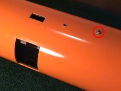 |
| Arming plug wired to battery clip | Complete payload section ready for mounting in airframe | A screw on each side holds the payload compartment in place inside the airframe |
Another centering ring sits atop the riser and is held in place with screw into the ends of the riser dowels. This completes the payload compartment assembly. It can now be slid into the airframe. After aligning the openings two screws hold it in place.
It should also be noted the the entire airframe was fiberglassed with 2 oz. cloth. This greatly increases the strength of the rocket but does add some weight. I was still learning the technique while building AYUCR so there was a lot of sanding to be done. If there is any advice I can offer it is to very aggresively rough the surface of the airframe to enhance to bond of the epoxy, wear gloves so you can use your hands to smooth out wrinkles and eliminate bubbles and buy a $20 palm sander.
| Back to Home | On to Booster |