Having wired the camera with external shutter leads I now needed a way to trip them. They needed to be tripped (i.e. connected together via a relay) at a regular interval, perhaps 2 seconds, starting at launch. I had read that a 555 timer chip configured as a multivibrator can work. I purchased Engineer'sas a timer. Mini-Notebook, 555 Timer Circuits (Radio Shack Cat. No. 62-5010) and found the basis for the circuit I would need.For launch detection I chose an acceleration switch from Adept Rocketry. The acceleration switch and timer were both powered by a single 9V battery.
|
| Electronics Block Diagram |
I built and tested the circuit using a breadboard and then implemented it using a Radio Shack PC board kit (Cat. No. 276-1576). This allowed me to etch my own PC board. If you decide the make your own board for the circuit you will need a 3/64" drill bit. These can be a little tough to find but larger drill bits will make holes that are too large and make soldering very difficult. I discovered this the hard way. I also recommed a socket for the 555 IC as heat from soldering can damage ICs. The ASA3T acceleration switch is smart enough to differentiate a bump or jar from liftoff but I chose to add an arming plug (1/8" Phono plug) just to be safe. Once prepped and loaded if the timer starts accidentally there is no way to stop it before it wastes a whole roll of film. While not strictly necessary it is recomended.
| Part | Radio Shack Cat. No. |
| 555 Timer IC | 276-1723 |
| 8-Pin Low Profile Socket | 276-1995 |
| 22 uF Capacitor | Various |
| 47k Ohm Potentiometer (R1) | 271-283 |
| 10K Ohm Resistor (R2) | 271-1335 |
| 5VDC SPDT Relay | 275-240 |
| 1N914 Switching Diode | 276-1112 |
| 9V Battery Snap Connector | 270-324 |
| Optional | |
| 1/8" Phone Jack (closed circuit type) | 274-248 |
| 1/8" Phone Plug (2 Conductor) | 274-278 |
The IC pin numbers are listed on the 555 IC. Starting from the top they are 8, 4, 3, 1, 2 and 6.
 |
| Timer Circuit Diagram |
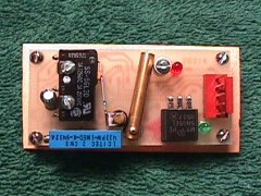
The finished board is shown below.
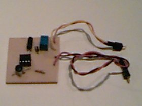 |
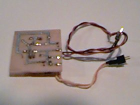 |
| Timer Circuit Component Side | Timer Circuit Trace Side |
The Yellow and Orange wires terminate in a Dean's connector and connect to the Camera's shutter wires. The Red and Black pair of wires connect to the output of an Adept ASA3T Acceleration Switch. This device (shown below oriented horizontally) senses liftoff and powers the timer circuit using via the same 9V bettery powering the ASA3T. There is a POT on the ASA3T that allows it to be configured to power up the timer anywhere from 1/2 to 15 seconds after liftoff. When used in AYUCR the time delay is set to the minimum.
 |
| Adept ASA3T Acceleration Switch |
Back to
| Back to Home | On to Payload Bay |