| Dimensions (HxWxD) | 2.5"x1.25"x5/8" |
| Weight | 12g (19g w/ battery) |
| Power Consumption | 4-12mA typical |
| Battery Life | 4 hours minimum |
| Power Requirements | 12V remote Battery or 6V-12V via external power connector |
| Serial Port | 2400 Baud, 8bits, No Parity, 1 Stop bit |
| G-Switch Rating | 2.1G +/- 10% |
| Parameter | Units | Explanation |
| Launch Detect | 1/100 sec | How long the rocket must accelerate at greater than 2.1 Gs to initiate liftoff. Range is 1/100 second to 2.5 seconds. A good choice is 20 (2/10 sec). Too short and the controller will be sensitive to bumps and shakes. Too long and the motor may burn out before launch is detected. |
| Launch Delay | 1/10 sec | Delay between launch detect and first picture. The default is 0 which gives shots during boost. If you only want shots starting at apogee add a delay for boost and coast here. |
| Number of Groups | Count | Pictures can be divided into any number of groups with a delay between groups. Use this to program the number of groups of pictues to take. |
| Number of Pictures | Count | This is the number of Pictures to take per group. If the Number of Groups is set to 1 (one) then this is effectively the number of pictures to take total. |
| Picture Interval | 1/10 sec | Delay between each picture in each group. The minimum is dependant on the camera used. See Trimming the Controller for more info |
| Group Interval | seconds | Delay between each group of pictures. There is no need to account for the Picture Interval when figuring the Group Interval. If the Picture Interval is 3 seconds and the Group Interval is 10 seconds the time between the last picture of the first group and the first picture of the second group will be 10 seconds not 13. |
| Shutter Speed | 1/10 sec | The amount of time the controller trips the shutter release button for. This has nothing to do with how long the shutter on the camera is opened for. See Trimming the Controller for more informatation. (not programmable in User Mode) |
| Servo Mode | 0 or 1-255 | Controls whether the controller is to be interfaced with an electronic shutter (0) or mechanical shutter via servo (1-255) (V1.65+) |
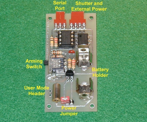
The Camera Controller is designed to be powered one of two ways. You can use a 12V remote control battery (Radio Shack part 23-154) in the on-board battery holder or connect an external 6V-12V battery via the Shutter/External Power connector. To use a 12V remote control battery insert it with the plus side facing up as shown
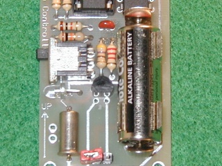
The on-board battery holder holds the battery very tight. You may need a pair of pliers to remove the battery.
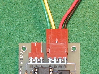
It is also possible to power the Camera Controller externally via the Shutter/External Power connector. A 9V battery connected this way will power the controller for much longer than the on-board battery. Depending on how the external power source is mounted it may also provide more reliable power under high G loads. On the Shutter/External Power connector pin 3 is positive voltage and pin 4 is ground. Be careful to observe polarity. In the picture below the red wire is positive and the black wire is ground.
Powering up the Controller - To power up the Controller place the red power jumper over the two pins on the power header. The LED should flash when powered up. To conserve the battery you should power the controller down unless you are flying it or programming it.
Standby Mode - Moving the Arming Switch to the OFF position (Up) puts the controller in Standby Mode. A slowly flashing LED, about 1 flash every two seconds, confirms the unit is in standby mode. This is the normal mode for controller unless the rocket is on the pad and ready to fly. In this mode the controller monitors the serial port and will accept commands to program the unit or dump the current flight parameters to the serial port.
User Mode - Most of the flight parameters may be field-programmed without the aid of a laptop or Palm computer using User Mode. User mode requires a small push button or shorting wire connected to the User Mode Header. Pressing this button or shorting the connections for approximately 2 seconds while in Standby Mode puts the unit in User Mode. User mode lets you reprogram the six most often used flight parameters, see the settings of the flight parameters and check the number of pictures taken during the most recent flight.
Data is entered by pressing and releasing the button. To enter a 5 press and release the button 5 times. Press and release the button surely at a rate of about two presses per second to ensure accuracy. A pause of approximately 1.5 seconds signals the end of user input. It should be noted that using this method a zero can not be entered. This is only really a problem for the Launch Delay parameter. In this case use a 1 (1/10 second) or program the controller with a computer if a delay of zero is necessary.
For commands with output the LED is flashed the appropriate number of times. Count the flashes to read the output. Unlike popular altimeters, numbers greater than nine are not displayed a digit at a time. A 4 followed by a 13 would be 4 flashes then 13 flashes not 4 flashes then 1 flash then 3 flashes. A zero is indicated by one longer flash.
Upon entering User Mode the LED flashes ten times quickly. This ten-flash is the prompt for one of four commands. These commands are numbered one through four and are entered by pressing and releasing the G-Swtich the corresponding number of times. After executing any of these commands except the Exit command the ten-flash prompt is repeated.
| Command | Explanation | |
| 1 | Display Program | The first six Flight Parameters are displayed one at a time in order by flashing the LED. |
| 2 | Enter Program | The controller prompts, with a single flash, for the first six Flight Parameters. respond by entering a new value for each using the switch-pressing technique discussed earlier. Shutter Speed and Servo Mode can not be specified using this command |
| 3 | Picture Count | Displays the number of pictures taken during the most recent flight. This is also displayed when switching from Post-Flight Mode to Standby Mode. Use this command to repeat it. |
| 4 | Exit User Mode | Returns to Standby Mode |
Armed Mode - Moving the Arming Switch to the ON position (Down) arms the unit. A quickly flashing LED indicates the controller is Armed. When Armed the controller waits for launch by watching the G-Switch. If it senses greater than 2.1 Gs for the duration specified by the Launch Detect parameter it will immediately enter Flight Mode and begin the picture cycle. You can disarm the controller and return to Standby Mode by moving the Arming Switch to the OFF position. If the controller loses power when armed it will automatically arm again when powered back up. If the unit is powered up armed but was not armed when powered down it will not auto-arm. This is to prevent unwanted pictures from being taken. You may reset it by disarming then rearming it.
Flight Mode - Once the controller has sensed liftoff it enters flight mode. If a Launch Delay has been specified the controller pauses that amount of time and then begins taking pictures according to the program. Once the program has run its course the unit enters Post-Flight Mode.
Post-Flight Mode - After the controller has taken the programmed number of pictures it enters Post-Flight Mode. It turns off the LED and puts itself into a low-power mode to help save the batteries. To reset the controller and enter Standby Mode place the Arming Switch in the OFF position. This wakes the unit up and it will flash out the number of pictures taken during flight. After that you should notice the slow flashing LED indicating Standby Mode. As the Arming Switch may be the only thing easily accessable from outside the rocket the picture count is designed to provide some quick feedback after flight. The picture count display only shows the number of pictures the controller tried to take. If there was a power failure in flight this number may be less than expected. This display cannot be used to diagnose problems with the camera or problems with Trimming. You should always check the camera's exposure counter to see if it agrees with the controller.
The camera shutter contacts are connected the controller via the Shutter/External Power connector. Pins 1 and 2 (yellow and green wires in the photo) are connected to the camera's shutter contacts. The Servo Mode parameter must be zero to enable electrical shutter mode.
The controller can also output a servo signal to control a mechanical shutter via a standard servo. If the Servo Mode paramenter is greater than 0 the controller will operate in servo mode. Instead of simply closing the shutter contacts for a time equal to the Shutter Speed parameter a PWM servo signal is sent to position a servo to take the picture. The servo starts at rest, moves a distance proportional to the value of Servo Mode, pauses according to Shutter Speed and then returns to rest. When at rest the controller outputs a 1ms pulse train. If Servo Mode parameter is 64 the servo will move to its 25% position to take the picture. If it is 128 the servo will move to 50%, etc. You can adjust Servo Mode and Shutter Speed to the settings that work best with your particular setup.
Different cameras require different settings for the Shutter Speed paramater. This isn't how long the camera shutter is actually open, that's controled by the camera, but how long the shutter pulse is that is sent to the camera. The default is 3/10 of a second. Your camera may require longer or shorter. The other setting that may vary is how long the camera takes to recycle between shots. If you are trying to get shots under boost it pays to find out ahead of time otherwise the camera may not be able to keep up and drop frames.
It is best to set this with the camera turned on and no film in it. Set the controller to take a picture every 3 seconds or so. Make sure everything is connected and simulate launch. You can simulate launch by shorting the connections of the User Mode Header. Ensure that the camera takes a picture each cycle. If it does not increase the Shutter Speed until the camera responds reliably to each command from the controller to take a picture. Once you have determined a reliable Shutter Speed setting you should probably never need to change it.
Next, adjust the Picture Interval setting downward until the camera begins to drop frames. Increase the Picture Interval until the camera keeps up with the controller. This is the minimum cycle time for your camera. Make a note of this value. You can make your flights with any value for the Picture Interval parameter as long as it is at least as long as the minimum. Some cameras will be able to cycle faster without film than with. The resistance of winding the film adds to the cycle time. If you have some old film or some of that cheap film they give away when you take a roll to be developed you should test if the minimum Picture Interval changes with film in the camera.
Below is a flight timeline from a sample flight to help clarify how the controller works.
| Flight parameter | Value |
| Launch Detect | 20/100 sec |
| Launch Delay | 0 sec |
| Number of Groups | 3 |
| Number of Pictures | 4 |
| Picture Interval | 2 sec |
| Group Interval | 5 sec |
| Shutter Speed | 3/10 sec |
| Servo Mode | 0 |
| Time | Event |
| -0.0 | Altimeter is armed. LED flashes quickly and controller waits for launch detect |
| 0.0 | Launch. Altimeter senses launch and confirms G-Switch closed for 20/100 sec |
| 0.2 | Valid launch. There is no delay before the first picture specified so the controller immediately begins to take pictures. |
| 2.2 | Picture 2 |
| 4.2 | Picture 3 |
| 6.2 | Picture 4 followed by a 5 second Group Interval |
| 11.2 | Picture 5 |
| 13.2 | Picture 6 |
| 15.2 | Picture 7 |
| 17.2 | Picture 8 followed by a 5 second Group Interval |
| 22.2 | Picture 9 |
| 24.2 | Picture 10 |
| 26.2 | Picture 11 |
| 28.2 | Picture 12 |
| 28.5 | Immediately following last picture controller enters Post-Flight Mode. LED is off and the controller waits to be disarmed. |
| 28.5+X | Arm Switch to OFF. LED flashes 12 times to indicate 12 pictures were taken. Enters Standby Mode. |
The controller recognizes seven commands via the serial port. One programs the controller with new flight parameters and the other instructs the controller to dump the current program to the serial port. These commands can be sent from the serial port of any computer with the serial port set to 24008N1 or 2400 baud, 8 data bits, no parity and 1 stop bit.
The serial port uses a three pin interface. Looking at the picture with the serial port facing up and going left to right the piout is as follows
| Pin | Function |
| 1 | TxD |
| 2 | RxD |
| 3 | GND |
Command Summary
| Command | Function |
| /P | Accept new flight parameters (for use with Palm software) |
| /D | Dump settings (for use with Palm software) |
| /N | Prompt for new flight parameters using a simple interface (V1.5+) |
| /R | Display the current fight parameters in human-readable format (V1.5+) |
| /V | Report firmware version (V1.5+) |
| /S | Test Shutter (V1.5+) |
Program - To download flight parameters to the controller the serial programming command is "/P" followed by eight bytes:
/ P p1 p2 p3 p4 p5 p6 p7 p8
where the data bytes are defined as follows
| Data Byte | Flight Parameter |
| p1 | Launch Detect (1/100 sec) |
| p2 | Launch Delay (1/10 sec) |
| p3 | Number of Groups |
| p4 | Number of Pictures |
| p5 | Picture Interval (1/10 sec) |
| p6 | Group Interval (seconds) |
| p7 | Shutter Speed (1/10 sec) |
| p8 | Servo Mode (0 or 1-255) |
The program that communicates with the controller should confirm that the controller responds with two bytes "OK" to ensure the command was received successfully. The controller will report "TO" if the eight parameter bytes are not received within a few seconds.
Dump - The command to instruct the controller to send its current Flight Parameters is "/D". Eight databytes in the same order sent in the Program Command will be be sent from the controller followed by the bytes "OK"
New Program (V1.5+)- This provides a simple user interface for accepting new flight parameters. It prompts for each parameter one at a time and allows the user to change the current value using the '+' and '-' keys. Type '/N' to enter this command. The prompts are as follows:
| Prompt | Flight Parameter |
| LD- | Launch Detect (1/100 sec) |
| DL- | Launch Delay (1/10 sec) |
| #G- | Number of Groups |
| #P- | Number of Pictures |
| PI- | Picture Interval (1/10 sec) |
| GI- | Group Interval (seconds) |
| SS- | Shutter Speed (1/10 sec) |
| MD- | Servo Mode (0 or 1) |
To increase the current value press the '+' key. To decrease the value press the '-' key. To reset the value to zero press the '0' key. To accept the current value press Enter. To canel press Esc, any changes will be discarded. Important: make sure that "Local Echo" is off in you terminal program or you will see a lot of garbage on the screen.
Read Program (V1.5+) - '/R' displays the current flight parameters in a human-readable format. The values are labled the same as the prompts in the New program command.
Initialize (V1.52+) - '/I' This resets the flight status from the values stored in the nonvolatile memory. The should really not have a noticable affect and is primarily for debugging.
Version (V1.5+) - Enter '/V' to see the current firmare version.
Shutter Test (V1.5+) - Enter '/S' to test the shutter. The controller will take one picture. This is useful for setting the Shutter Speed parameter.
Errors
The controller will report the following errors. "TO" is reported if a command letter is not entered after the slash character within 2 seconds. "ER" is reported if an unknown command is entered.