The deployment and recovery system employed by AYUCR is somewhat unique. I have never seen anything quite like it used in other camera projects so I thought I would devote an entire section to it. What makes AYUCR unique is how the parachute for the payload section is rigged. Other camera projects I had seen recover the rocket in a conventional manner under a single chute. This causes several problems. After separation the payload section can crash back into the booster, possibly damaging the camera or interfering with the pictures. Also, the payload section may not be oriented properly to take good pictures. I want pictures of the launch site not the sky. I decided to have the booster and payload recover on separate chutes. Then there is the problem of ejection reliability. Motor ejection failures are often the result of user error but they can also happen to the best of us. Delay times are also not very accurate. Lawndarting the camera and electronics is unacceptable and due to the way the chutes are rigged I needed separation reliably at apogee. I decided to use and altimeter to deploy the chutes at apogee and retained the motor ejection for backup.
| | |
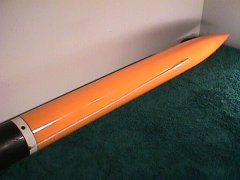
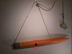
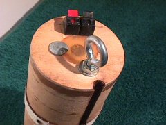
| Payload section hanging on its plumb line | Altimeter can attachment bolt | Nose cone attachment point |
Most of the pictures AYUCR would take would be on descent so I wanted to make sure the camera would be oriented properly during recovery. Attached to the payload section at each end is a plumb line with a knot near its center. The knot is tied to a two foot length of bungie which is connected to a heavy-duty swivel and then to a 42" Top-Flight X-form parachute. I wanted to minimize swing which might blur the pictures and the X-form chute has worked out very well. A swivel is necessary though as X-forms have a tendency to spin twist up the shroud lines. The plumb line is strong nylon rope and is attached to a bolt on the altimeter can and to a hole through the nose cone right above the shoulder. A knot in the line holds it in the nose cone and permits adjustment (there is a foot of slack in the nose not shown.) A screw shown above holds the nose cone in place.
Originally the knot in the center of the plumb line was attached directly to a swivel and then to a parachute. On the second flight though the payload section was recovered with the altimeter can screw-eye bent at a 90 degree angle. Apparently the shock of the chute opening was too much for the screw eye. It didn't break but if it did it could have been a disaster. I improved the design for later flights by replacing the screw-eye with a thicker, stronger one and leaving less of the shaft exposed (the first one had about 2" exposed) I also added the two feet of bungie shown above. I was concerned that adding bungie might blur the pictures by bouncing around but in practice it seems to work fine with no noticeable bouncing.
 | 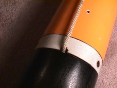 |  |
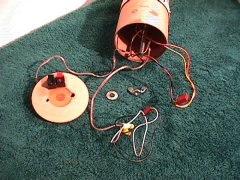
| Plumb line in groove in altimeter can | Notch in altimeter can allow plumb line to exit | Plumb line flat against airframe |
The plumb line is long enough to lie flat against the airframe for launch. There is a grove in the altimeter can that accepts the plumb line so that the booster can be mated with the payload section. A notch allows the booster to mate cleanly. The chute for the payload section is packed in the booster and is protected from the altimeter pyro charge by a piece of Nomex cloth. When the charge fires the halves separate pulling the payload and booster chutes from the booster section. For the maiden flight I packed the payload chute below the booster chute in the hopes that the payload chute would pull out the booster chute. This just lead to a tangle that almost destroyed the whole rocket. Luckily one of the chute opened and the whole thing came down, hard, under the single chute. In later flights I have packed the chutes in reverse with the payload chute on top of the booster chutes but with a small piece of masking tape connecting them. This prevents the tangles and the tape pulls the booster chute out. The tape is so small that it breaks easily giving a clean separation.
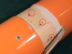 |  |
| Multiple holes for various "roll" angles | Camera opening rolled to the right |
The nose cone has holes every inch or so around the shoulder. This allows me to "roll" the camera opening to the right instead of allowing it to point straight down. I have experimented with various angles and have found that some roll makes for better, more varied shots. Having all the shots straight down results in too many pictures of the same thing, only from different altitudes.
 |  |  |
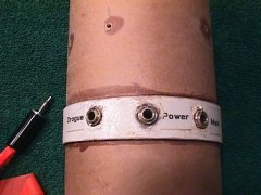
| Altimeter can screw-eye and pyro jacks | Notice the square hole for carriage bolt | Wiring harness for Adept ALTS-2 |
AYUCR uses an altimeter to control main deployment. In addition the booster is designed to allow the motor ejection charge to act as a backup. I mainly chose to use the altimeter to ensure deployment as close to apogee as possible. This helps reduce stress on the payload section because the parachute is deployed when the rocket is moving its slowest. So far this has worked very well and as a bonus I know how high the pictures were taken from. Theoretically I could time the descent of the payload section and knowing the time between pictures and assuming a constant rate of descent I could get a fairly accurate altitude for each and every picture. Remind me to try that some day if you think it might be interesting.
The design of the altimeter can is fairly standard. It is based on the design presented in January/February 1997 Sport Rocketry. I made some modifications such as adding shorting plugs for each ejection charge for added safety and adding spring type speaker wire connectors to connect the flashbulb charges to. This is a great time saver and I highly recommend it. The jacks if kept clean seem to be very reliable and hold the wires tightly. The ones I used are available at RadioShack and actually come in a strip of eight. They can be cut apart and epoxied in place quite easily. If you can't seem to find them I will look up the part number for you.
The groove in the altimeter can that accepts the plumb line was made by cutting out a slit using a hobby knife and then epoxying a 1/4" launch lug split down the middle on the inside. This forms a channel in the lower half of the altimeter can and firms up the coupler. The aft cap for the altimeter can is notched to allow room for the channel as shown in the above photo.
 |
| Altimeter can arming jacks |
| Back to Home | On to Mirror Assembly |